USB HID Phone - A FeTAp 611 rotary dial as a USB keypad
Summary
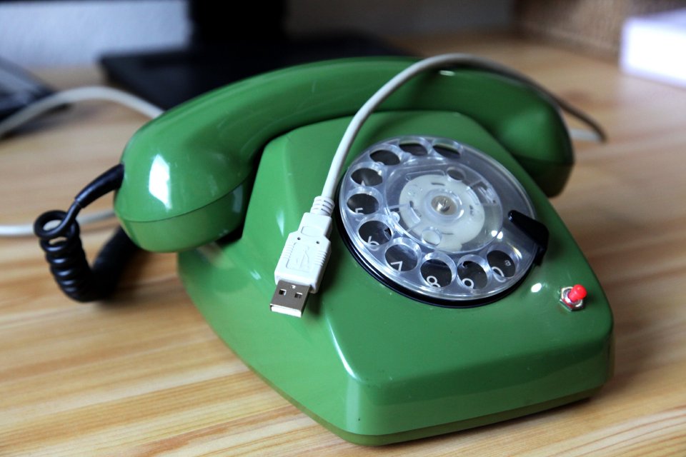
A FeTAp 611 rotary-dial telephone, the iconic Deutsche Bundespost desk phone - converted into a standard USB HID keypad. Plug it into any computer with USB 1.1, no additional driver needed, install no software: just dial a digit on the rotary disc and the host sees a normal HID keypad keystroke.
The conversion is non-destructive on the dialing mechanics: the original nsa (off-normal) and nsi (pulse) contacts are reused as inputs to a small PIC18F2550 running a four-state pulse-counting state machine. The MCU then emits a USB HID keyboard report.
Demo
In the video the USB HID Phone is plugged into a Windows notebook running sipgate softphone software. sipgate accepts ordinary keypad / keyboard input to enter the number to call, so to it the rotary dial just looks like a regular numeric keypad. I dial my own cell phone number on the FeTAp 611 - and my cell phone actually starts ringing. Fun fact: It’s a Motorola RAZR foldable GSM phone playing the “The Beginning” SID tune (Jeroen Tel, 1987, Maniacs of Noise, from the HVSC; play it in the browser) as ring tone.
In the second video I explain the basics of the USB HID Phone and do a demo with a calculator on the command line.
Background story
I originally built a first version of this project back in 2008 as a quick hack. Jan and I had a beer and then we wondered about a most useless but still nerdy electronic project. So the idea was born to build a rotary-dial phone acting as a USB HID keyboard. The phone itself was purchased from ebay. Though I no longer design using through-hole components, I decided to re-do schematic and PCB for you as a simple learning example. And after all these years, as of 2026 all parts can still be bought, from e.g. Reichelt. On my YouTube video people asked for a deeper explanation, so this is the long-overdue revisit:
- a freshly drawn schematic and PCB in KiCad,
- a clean rotary-dial pulse-counting FSM in C,
- and an interactive simulator of that FSM you can play with right in the browser.
How the rotary dial works
A FeTAp 611 rotary dial gives us two digital signals:
nsa(off-normal contact, MCU pin RB6): goes high while the dial is active (away from rest).nsi(pulse contact, MCU pin RB7): pulses low once per pulse during the spring-driven return.
The encoding is the historical loop-disconnect rule:
One pulse means digit “1”, two pulses mean “2”, … and ten pulses mean “0”.
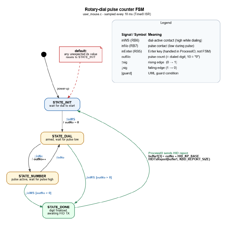
The FSM counts nsi falling edges only while nsa is high. On the last pulse, nsa falls together with the final ↑nsi; in_nsi then stays high with no further pulses, so no software subtraction is needed.
The state machine
A minimal four-state FSM, sampled every 10 ms by a Timer0 ISR, is enough:
| State | Meaning |
|---|---|
STATE_INIT |
Wait for the dial to start (↑nsa). |
STATE_DIAL |
Armed, waiting for the next pulse low. |
STATE_PULSE_LOW |
A pulse is currently active (nsi low). |
STATE_DONE |
A digit is finalized: main loop sends HID report. |
On ↑nsa we arm and reset pulseCount. Each ↓nsi increments pulseCount. When ↓nsa arrives and pulseCount > 0, the digit is finalized and the main loop emits a HID keyboard report containing pulseCount + HID_KP_BASE, then drops back to STATE_INIT.
If you want to see and step through the FSM live in your browser, head over to:
- FSM simulation: interactive timing diagram, scenarios for every digit (including “0” = ten pulses) and a manual-driven mode.
Hardware
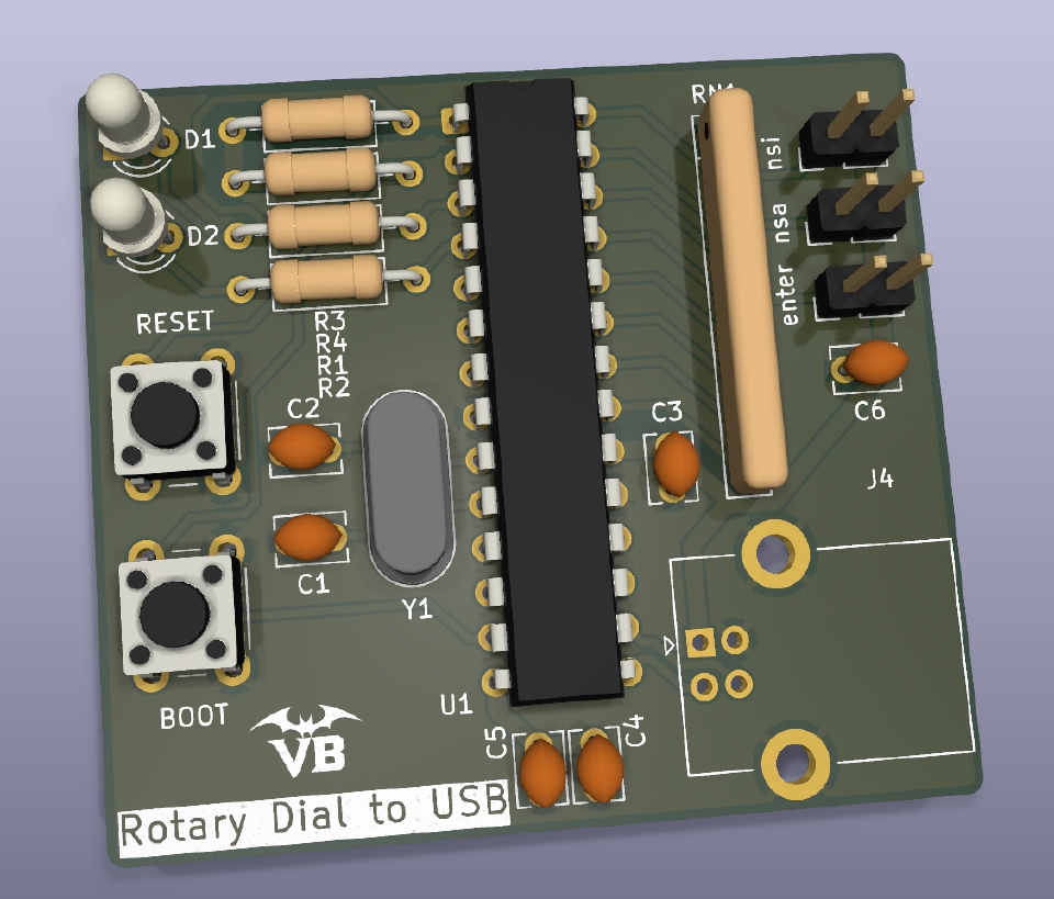
A through-hole, low-parts-count board around a PIC18F2550 with full USB peripheral. USB bus-powered, 20 MHz crystal.
Connection points:
- USB-B (through-hole connector)
- NSI contact (PCB solder holes)
- NSA contact (PCB solder holes)
- Enter input (PCB solder holes for an external push button)
Note: the new KiCad schematic and PCB are a redesign of an old, verified breadboard. The redesigned PCB itself has not been re-verified in real life yet.
- KiCad schematics and board layout: https://gitlab.com/vampire-bytes/usb-hid-phone
For the original FeTAp 611 dial wiring see the Wikipedia schematic of the FeAp 611.

Software
Firmware for the PIC18F2550, based on the classic Microchip mouse_keyboard USB HID example, with the rotary-dial FSM bolted on top of InterruptHandlerHigh() and a thin ProcessIO() that turns pulseCount into a HID keyboard report.
- Firmware repository will be released: link will appear here.
Why bother
Because a 1960s-era electromechanical input device sending modern, driver-less HID keystrokes is exactly the kind of thing this site is about. Also: it actually works, repeatably, every digit including “0”.
Modern successor
The same idea, ~17 years later, with current parts and CircuitPython instead of PIC C: Adafruit published a Rotary Phone Dial Keypad guide in 2025 that turns a Western Electric Model 500 rotary phone into a USB number pad using the KB2040 (RP2040) board. Same loop-disconnect pulse-counting trick, just on a modern microcontroller and toolchain, nice to see the approach is still alive and well.
-
FSM simulation: Rotary-dial pulse counter
Interactive in-browser simulator of the four-state rotary-dial pulse-counting FSM used in the USB HID Phone firmware. Step through each digit, watch in_nsa / in_nsi, pulseCount and the active state in sync.